CPUKewler v1.20000711
The CPUKewler is a device I designed primarily to cool a CPU using a peltier thermoelectric module. The difference to the normal CPU-cooling using heatsinks is that with the peltier you don't depend on the surounding air to lower the temperature. Instead electricity is used to extract the heat from the head-plate of the CPU, and guide it to the heatsink. This is accomplished through the peltier module.
This modules utilise the Peltier Effect that was discovered in 1834 by John-Charles-Athanase Peltier, a French clock maker and part-time physicist. In short terms Peltier Effect is a thermocoucple operating in reverse way. Instead of using the two distinct materials (usually copper and bismuth) to generate electron flow from heat, you insert a potential difference to them. The current that flows makes one side get hot, and another get cold. Energy (thus heat) is absorbed from one side and emitted from the other. The more you cool the 'warm' side the more cold the 'cold' side gets, and vice-versa. And there you have it... a cooler on one side and a heater on the other side. The temperature differential in no-load environment is typically at 70C-80C and the device tries to keep this difference when loads are used and heat is externally absorbed or applied, by drawing more and more voltage and current from the power source (until it reaches it's physical limits). You can get -20C on one side and +50C on the other. Pretty cool wouldn't you say? :)
The use of a peltier to cool or heat a small or medium sized object is probably the best way. You don't have any moving parts, no use of chemicals, no maintenance required, compact size, and only two wires and some electricity. Depending upon the size and heat dissipation/requirements of the object the proper peltier could do the job with some voltage and a few amperes. Many versions of peltiers are available in the market ranging from a few watts to hundrends. The price, power requirements, and size, are analogous to the power. Also 'stacking' could be used. Two or more peltiers in series (like batteries) make a very powerfull heat pump.
OK.. you get a peltier and put the 'cold' side on the object you want to cool down and the 'warm' side on a heatsink. Don't forget that the warmer the 'cold' side gets, the warmer the 'warm' side gets, and if you want to keep the object cold you have to cool down the 'warm' side of the peltier. This makes easy the use of medium class heatsinks as the energy to be dissipated is quite a lot (temperatures could reach 50C-60C), thus making better use of the ambient air (usually at 30C-35C). When only a heatsink is used to cool an object from temperatures close to the ambient one, you need a grate degree of efficiency. Now after you connect the power you flip the switch and you watch the object cooling down. The temperature keeps droping until you see notice crystals forming on the cold side. These crystals are water molecules that once were floating in the air (and playing the role of humidity) which were cooled enough by the peltier and became ice. This will happen always when the peltier reaches temperatures close to zero. The more air humidity exists and higher ambient air temperature, the higher the temperature threshold for the vaporated water to become liquid. And this is your worst nightmare when using peltiers... especially if want to cool an electronic device or anything else sensitive to corosion. The least thing that could happen is a small short-circuit, and the worst thing the oxidation of the PCB tracks. The solution? Simple... don't let the object get below a certain temperature. Switch-on the peltier when it gets too hot, and off when it gets too cold. That's what my CPUKewler was designed to do.
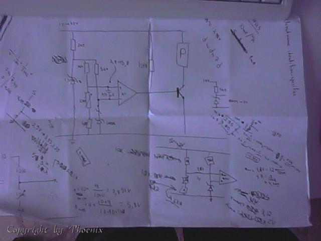
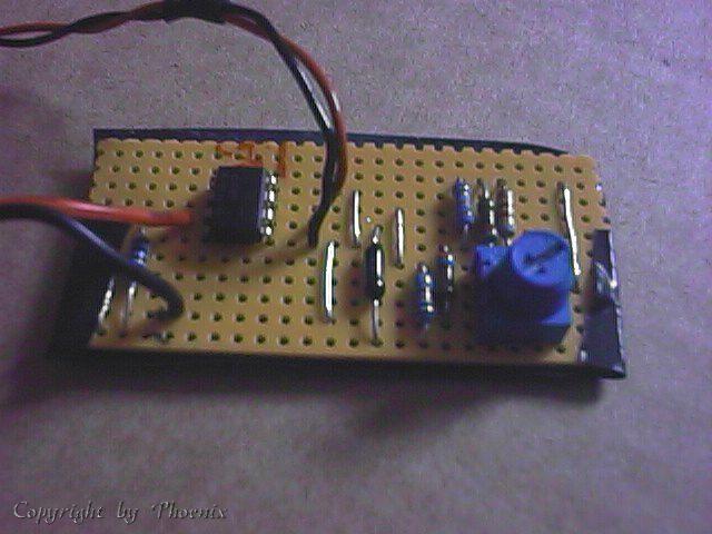
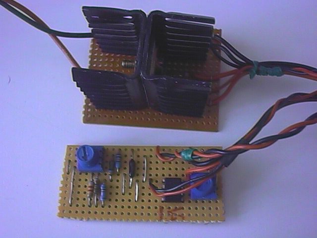
The objective of this project was mainly to help me understand and practice the operation of a peltier device. The main schematics were drawn in a piece of paper (no Protel, no OrCAD), and the components selected on a found-suitable-accepted basis. No specific search was done (only price-watch). The device consisted of three parts. The temperature controller, the power-transistor, and the peltier/thermometer. As temperature controller the LM311P op-amp was used. The LM335 thermo-diode was used to measure the temperature of the CPU (10mV/K) and in conjuction with a reference voltage from a variable voltage divider assembly, the op-amp was set to switch on and and off the peltier when the CPU exceeded or droped bellow the required temperature respectively. The op-amp (open collector output) with a pull-up resistor was driving the TIP-3055 power transistor which was capable of providing the required by the peltier amount of current. The peltier was a 9.6W Supercool with aproximate maximum values: 3.2V, 3A, D8max=70C. The device was powered from the +5V line of the PC's PSU.
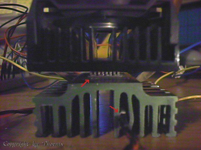
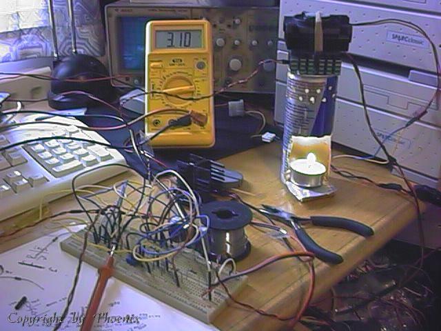
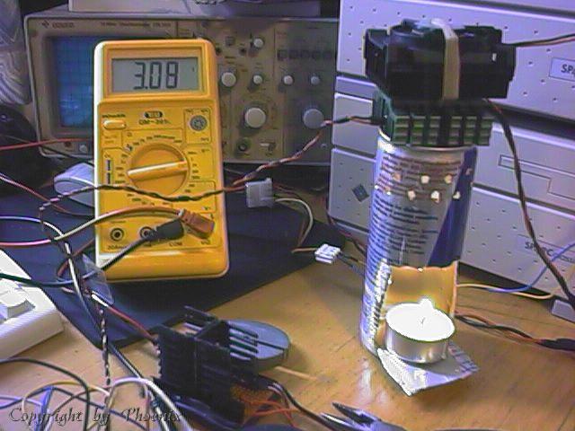
The first tests were done to test the operation of the temperature sensors. The peltier was attached to two heatsinks, one with a fan at the 'warm' side, and one bare at the 'cold' side. Heatsink paste was used in all bindings to improve heat transfers. The diode was placed between two fins of the 'cold' side. The tests were successfull and some observations about the responce time and accuracy of the diode and thermostat were done.
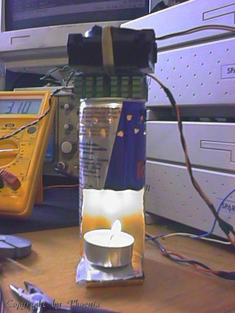
The next stage was to do a simulation in the required operating condidions. For this reason a custom made 'CPU emulator' with variable load was designed using an empty Red-Bull can, a tea-light candle, and one slim AAA battery. The 'emulator' was set to provide just enough heat to the heatsink so that it could raise the temperature a few degrees. Then the device was switched on. The heatsink was at aproximately 37C at the beginning. After a while it started falling to 35C , 34C, and after a while stabilised at 31C. I did a few other tests and the final results showed that this peltier was not very powerfull. Because the heat source was quite a lot more powerfull than a typical CPU and the 'load control' was not very reliable, I decided to build the prototype board and do a test with a real CPU.
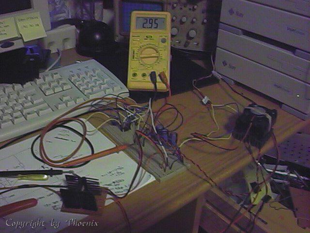
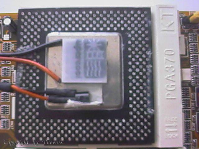
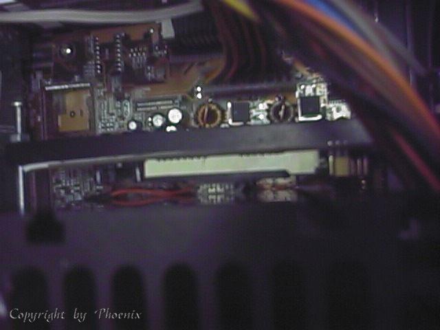
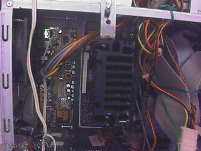
The prototype board was ready for testing, after a few modifications to the original schematic were done in order to control directly the maximum current for the peltier (via the transistor's input pull up resistor). The new prototype was ready and the peltier with the thermo-diode were placed on the head of my CPU (p2 celly). I used an adhesive thermal pad instead of normal paste, because the peltier and the diode had to be steady in their places. Also it was a good time to test the thermal ability of the pads. I assembled the "CPU card-peltier-heatsink" and put it back in my box.
I did many tests with many compibantions of MHz and core voltage and I finally realised that my first suspicions were true. The peltier was capable of cooling my CPU in standard settings and at some higher speeds/voltages, but not sufficient enough for my goal (666MHz, using an undocumented setting of my motherboard). The project was finished. Although it didn't work as expected I gained a lot of understanding about how peltiers work. Also I realised (one more time) that 'digital' is better than 'analogue'. The controller circuit although worked fine it didn't have the accuracy needed (when the min-max limits have a few degrees difference with 10mV per degree measurements, the system must have a very good accurady and fast responce). For this reason I desided to do an addition to my other project called 'Therm0', and use one of it's sensors (or even the internal thermistor of the CPU), and one outputs to control a more powerfull peltier (hopefully a 72W one) using a power MOSFET. When I gather the required money for the independent PSU needed and the peltier, I will continue the project.
Keep in touch for CPUKewler v2 Therm0 addon module.
phoenix
|